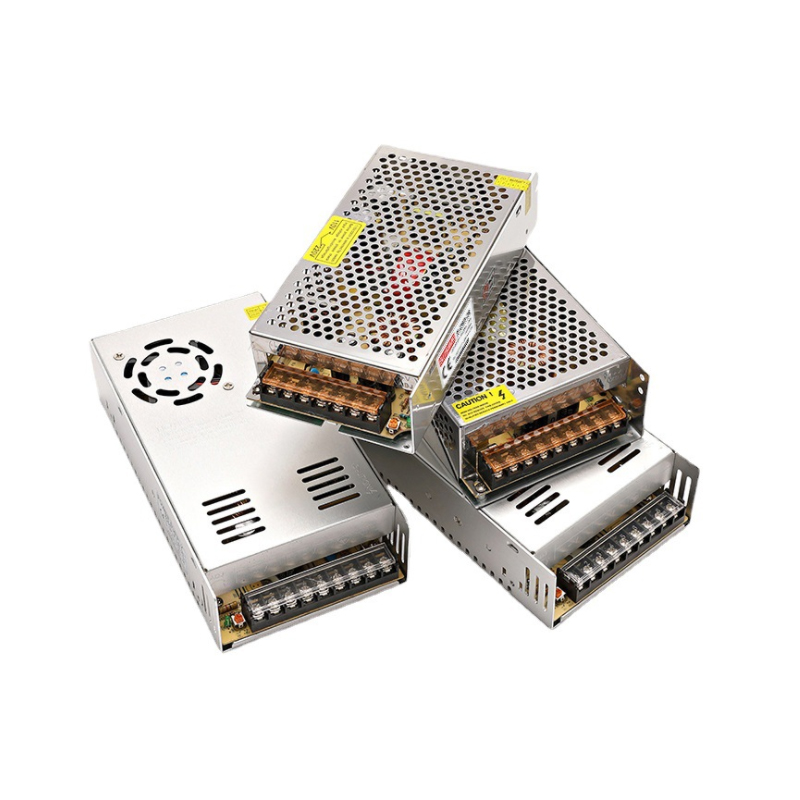
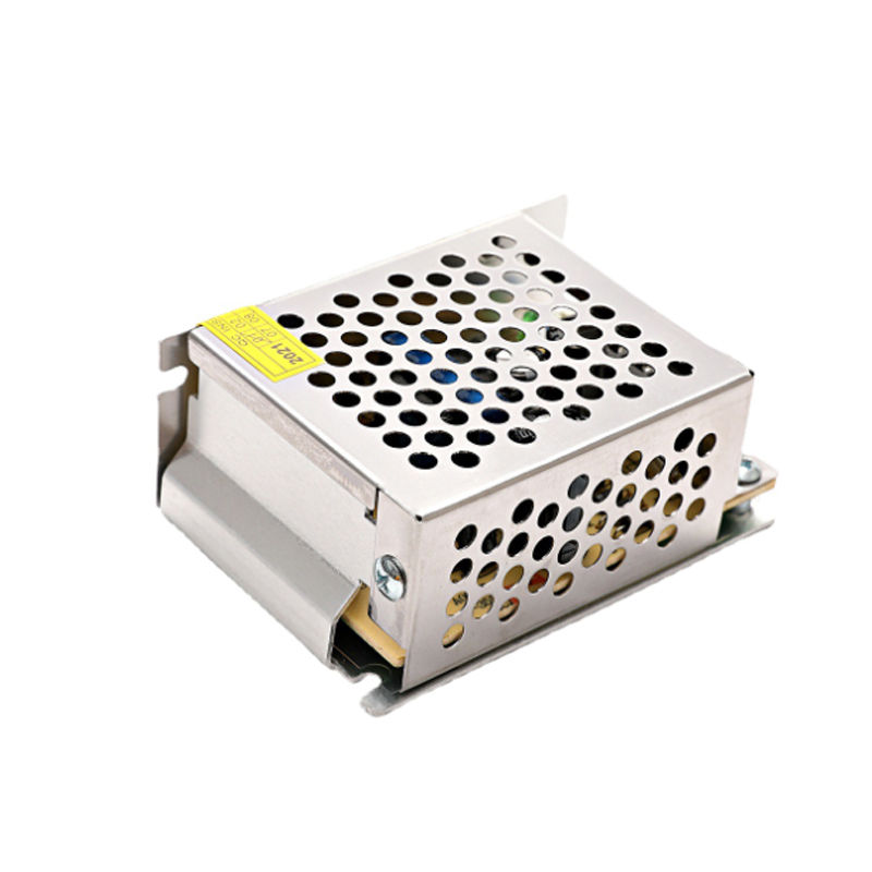
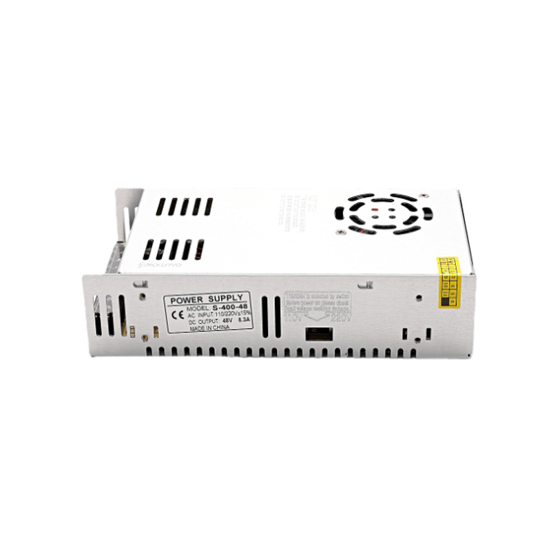
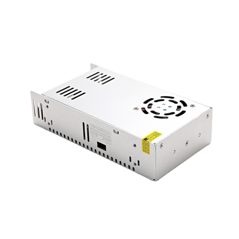
The constitute of Switching Power Supply
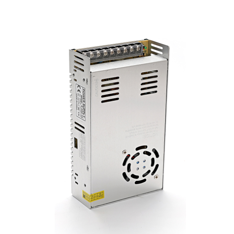
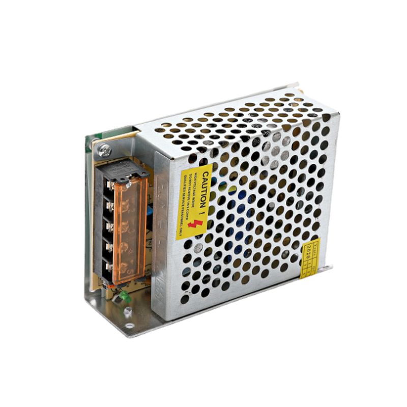
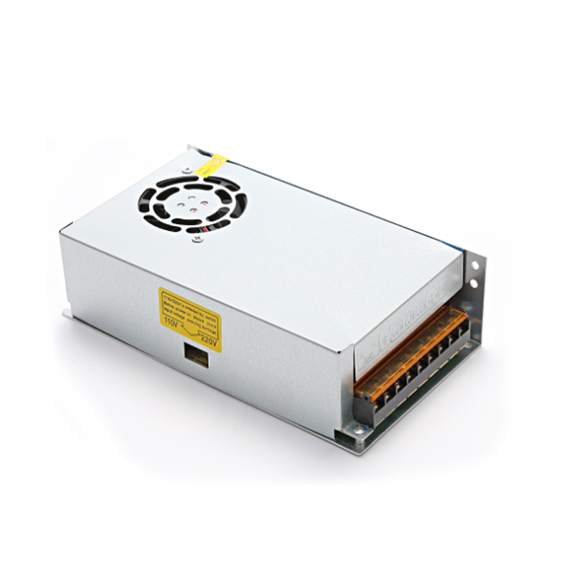
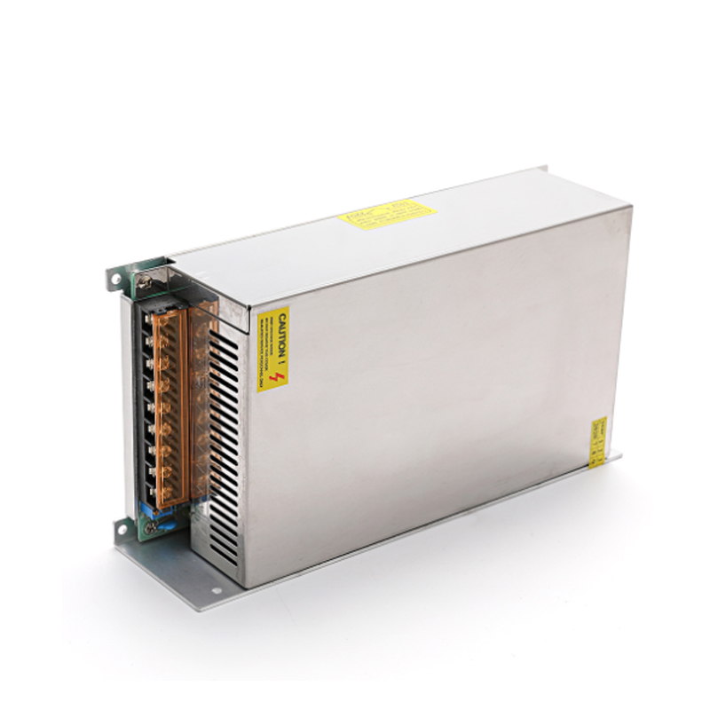
The switching power supply is roughly composed of the main circuit, the control circuit, the detection circuit and the auxiliary power supply.
1. Main circuit
Inrush current limiter : Limit the inrush current on the input side when the power is turned on.
Input filter: Its function is to filter the clutter existing in the grid and prevent the clutter generated by the machine from being fed back to the grid.
Rectification and filtering: rectify the AC power of the grid directly into a smoother DC.
Inverter: Convert the rectified direct current into high-frequency alternating current, which is the core part of the high-frequency switching power supply.
Output rectification and filtering: Provide stable and reliable DC power according to the needs of the load.
2. Control circuit
On the one hand, take samples from the output end, compare with the set value, and then control the inverter to change its pulse width or frequency to stabilize the output; The control circuit performs various protection measures for the power supply.
3. Detection circuit
Provides various parameters and various instrument data in operation in the protection circuit.
4. Auxiliary power supply
Realize the software (remote) startup of the power supply, and supply power for the protection circuit and the control circuit (chips such as PWM).
The Main Classification of Switching Power Supply

In the field of switching power supply technology, people develop related power electronic devices while developing switching frequency conversion technology. The direction of anti-interference development. Switching power supplies can be divided into two categories: AC/DC and DC/DC.
Miniature low power switching power supply
Switching power supplies are becoming popular and miniaturized. Switching power supply will gradually replace all applications of transformers in life. The application of low-power miniature switching power supply should first be reflected in digital display meters, smart meters, mobile phone chargers, etc. At this stage, the country is vigorously promoting the construction of smart grids, and the requirements for electric energy meters have been greatly increased. The switching power supply will gradually replace the application of transformers in electric energy meters.
Inverted series switching power supply
The difference between the inversion series switching power supply and the general series switching power supply is that the output voltage of this inversion series switching power supply is a negative voltage, which is exactly opposite to the positive voltage output of the general series switching power supply; and due to the energy storage The inductor L only outputs current to the load when the switch K is turned off. Therefore, under the same conditions, the output current of the inversion series switching power supply is twice as small as that of the series switching power supply.
The Working Principle of Switching Power Supply
The working process of the switching power supply is quite easy to understand. In the linear power supply, the power transistor is operated in the linear mode. Unlike the linear power supply, the PWM switching power supply makes the power transistor work in the on and off states. In the state, the volt-ampere product applied to the power transistor is very small (when it is turned on, the voltage is low and the current is large; when it is turned off, the voltage is high and the current is small) / The volt-ampere product on the power device is the power semiconductor losses on the device.
Compared with the linear power supply, the more effective working process of the PWM switching power supply is realized by "chopping", that is, the input DC voltage is chopped into a pulse voltage whose amplitude is equal to the input voltage amplitude. The duty cycle of the pulse is adjusted by the controller of the switching power supply. Once the input voltage is chopped into an AC square wave, its amplitude can be stepped up or down through a transformer. The output voltage value can be increased by increasing the number of secondary windings of the transformer. Finally, these AC waveforms are rectified and filtered to obtain a DC output voltage.
The main purpose of the controller is to keep the output voltage stable, and its working process is very similar to the linear form of the controller. That is to say, the functional blocks of the controller, the voltage reference and the error amplifier, can be designed to be the same as those of the linear regulator. The difference between them is that the output of the error amplifier (error voltage) goes through a voltage/pulse width conversion unit before driving the power tube.
There are two main working modes of switching power supply: forward conversion and boost conversion. Although the layout of their various parts differs little, the working process varies greatly, and each has its own advantages in specific applications.
Working Conditions of Switching Power Supply
1. Switching: Power electronic devices work in a switching state instead of a linear state
2. High frequency: Power electronic devices work at high frequency instead of low frequency close to the power frequency
3. DC: The output of the switching power supply is DC instead of AC
The Operating Mode of Switching Power Supply

As the name implies, switching power supply is to use electronic switching devices (such as transistors, field effect transistors, thyristors, etc.) to make the electronic switching devices "on" and "off" continuously through the control circuit, so that the electronic switch The device pulse-modulates the input voltage, thereby realizing DC/AC, DC/DC voltage conversion, as well as adjustable output voltage and automatic voltage regulation.
Switching power supply generally has three working modes: frequency, pulse width fixed mode, frequency fixed, pulse width variable mode, frequency, pulse width variable mode. The former working mode is mostly used for DC/AC inverter power supply, or DC/DC voltage conversion; the latter two working modes are mostly used for switching regulated power supply. In addition, the output voltage of the switching power supply also has three working modes: direct output voltage mode, average output voltage mode, and amplitude output voltage mode. Similarly, the former working mode is mostly used for DC/AC inverter power supply, or DC/DC voltage conversion; the latter two working modes are mostly used for switching regulated power supply.
According to the way the switching devices are connected in the circuit, the switching power supply can be roughly divided into three categories: series switching power supply, parallel switching power supply, and transformer switching power supply. Among them, transformer switching power supply (hereinafter referred to as transformer switching power supply) can be further divided into: push-pull type, half-bridge type, full-bridge type, etc.; according to the excitation of the transformer and the phase of the output voltage, it can be further divided into: forward excitation type , flyback, single-excitation and dual-excitation; if it is divided into use, it can be divided into more types
The Application of Switching Power Supply?
Switching power supply products are widely used in industrial automation control, military equipment, scientific research equipment, LED lighting, industrial control equipment, communication equipment, power equipment, instrumentation, medical equipment, semiconductor refrigeration and heating, air purifiers, electronic refrigerators, liquid crystal displays, LEDs Lighting, communication equipment, audio-visual products, security monitoring, LED light strips, computer cases, digital products and instruments and other fields.


- Главная страница
- Товар (по запросу)
- Акустическая составляющая
- Охранная сигнализация
- Датчик
- Пьезо Керамика
- Разъем и кабель
- Предохранитель и автоматический выключатель
- Переключатель и индикатор
- Держатель батареи и разъемы
- Двигатели, вентиляторы и радиатор
- Источник питания
- Реле и розетка
- Ультразвуковая машина и часть
- Светодиодный и светодиодный дисплей
- Wi-Fi и антенны
- Индуктор и дроссель
- Инструменты электрика
- Электронный прибор красоты
- ИС и полупроводники
- Плесень и пластиковый корпус
- Умный дом
- Ардуино и робот
- Для решения проблемы
- О нас
- Новости компании
- контакты

